
Hantek 100MHz DSO2D10 Dual Channel Oscilloscope + 25MHz AWG
Buy it now
$548.53 excl. GST
$630.81 incl. GST
Optional extras
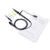 |
Extra Probe Hantek Oscilloscope Probe - 100MHz | $17.25 incl. GST |
Shipped Nationwide
In Stock with Supplier est. 13 days lead time
When will I receive it?
13 days sent via NZ Post (estimated lead time - requires sea freight)
Contact Us for a firmer ETA.
Staff Review
Coming with a waveform generator at this price… a no-brainer. It’s two bits of test gear in one unit. Feed test signals into the devices you’re testing and observe the results. We’ve used this scope for troubleshooting audio amps, it’s fantastic.
Video
Description
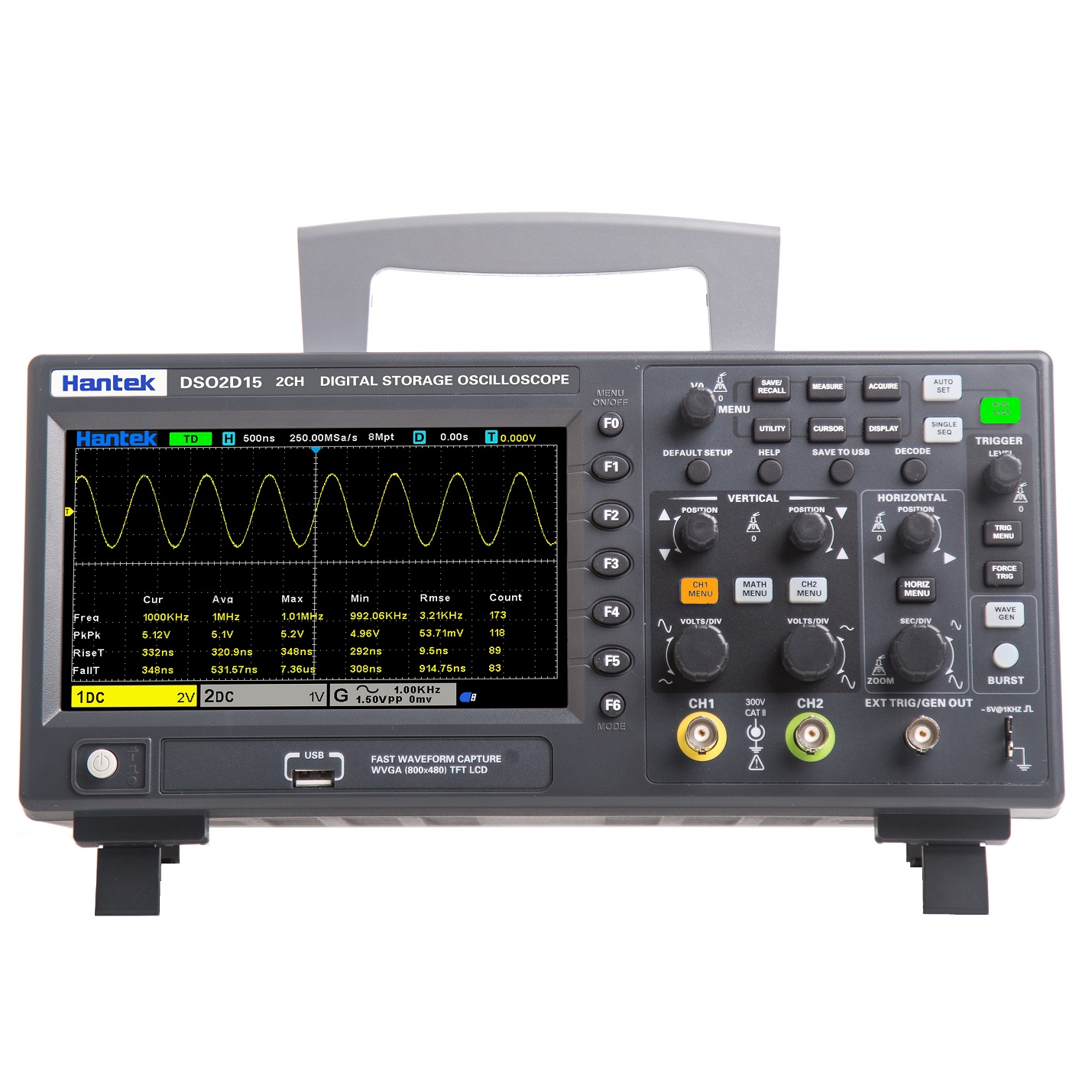
- 2 channels with independent control knobs
- 100 MHz analog channel bandwidth options
- Sampling rate up to 1 GSa/s
- 8M memory depth for waveform accuracy
- Vertical range 2mV/div to 10V/div
- Vertical resolution: 8-bit
- Advanced trigger modes: Edge, Pulse, Video, Slope, Overtime, Window, Pattern, Interval, Under Amp, UART, LIN, CAN, SPI, IIC
- Serial bus decode and protocol analysis: RS232/UART, I2C, SPI, CAN, LIN
- Supports multiple data formats: settings, waveforms, reference waveforms, CSV, images
- 3-digit digital voltmeter and 6-digit hardware frequency counter
- 32 auto measurements with statistics (max, min, standard deviation, etc.)
- 2 sets of digital voltmeters
- 25MHz AWG (Arbitrary Waveform Generator)
- Threshold testing and free on-screen measurements
- Supports SCPI remote command control
- USB Host/Device connectivity

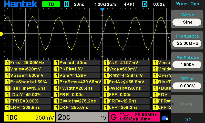
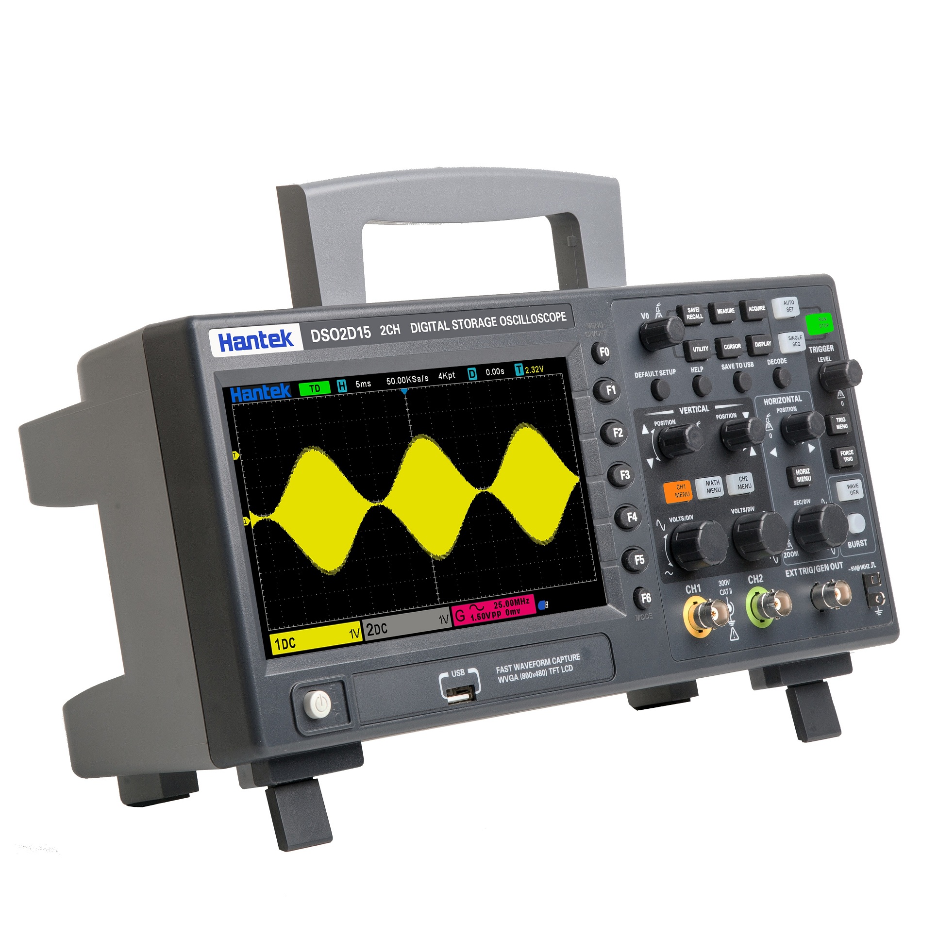
25MHz Arbitrary Waveform Generator
1CH 25MHz waveform generator, supports arbitrary waveform and burst output.
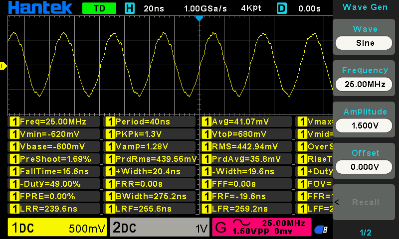
32 kinds of auto measurements with statistics
Provides real-time measurement and statistical analysis functions.
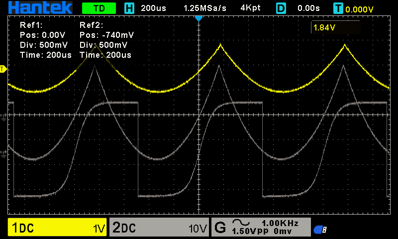
Save and export data
Supports saving up to 9 reference waveforms, CSV data, settings, and USB one-click screenshots.
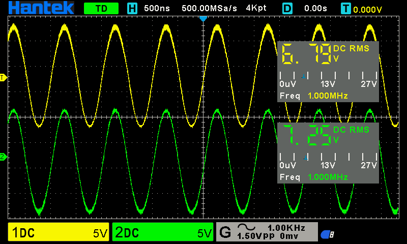
Digital voltmeter functions
Includes 2 sets of DVM, a 3-digit voltage meter, and a 6-digit frequency indicator.
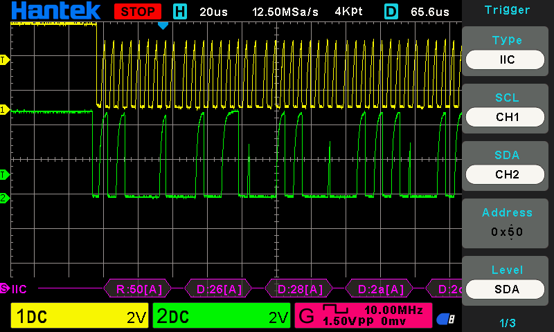
Serial bus trigger and decode
Supports protocol monitoring for UART, CAN, LIN, SPI, and I2C.
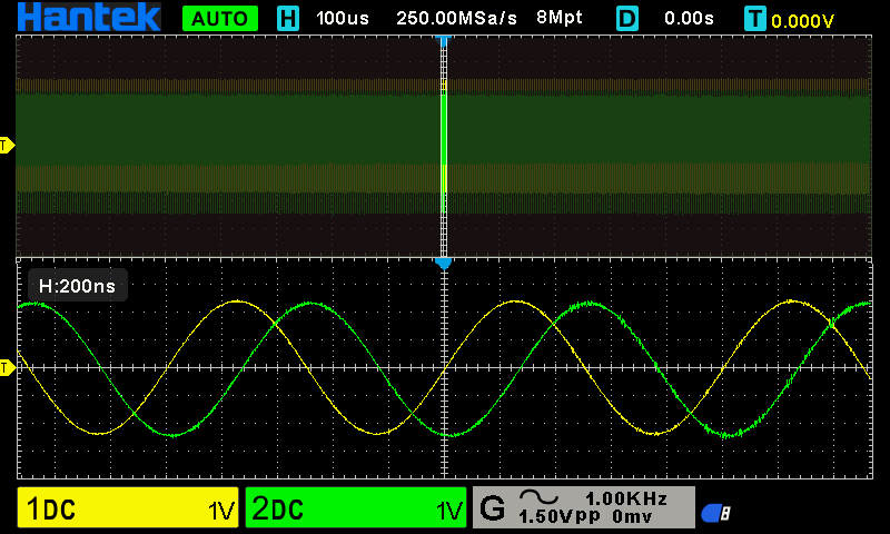
8M memory depth
Reduces waveform distortion and restores real waveforms.
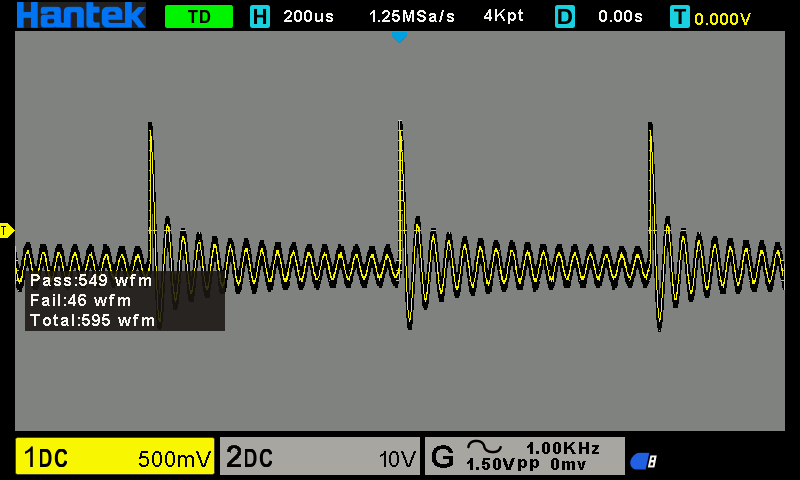
PASS/FAIL testing
Provides quick pass/fail analysis for waveform testing.
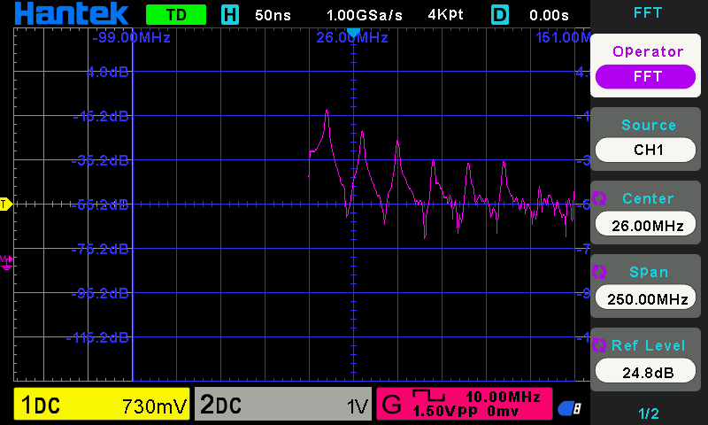
Math operations and FFT
Supports addition, subtraction, multiplication, division, and FFT spectrum analysis.
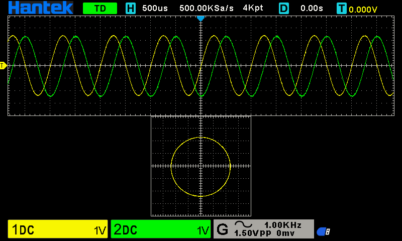
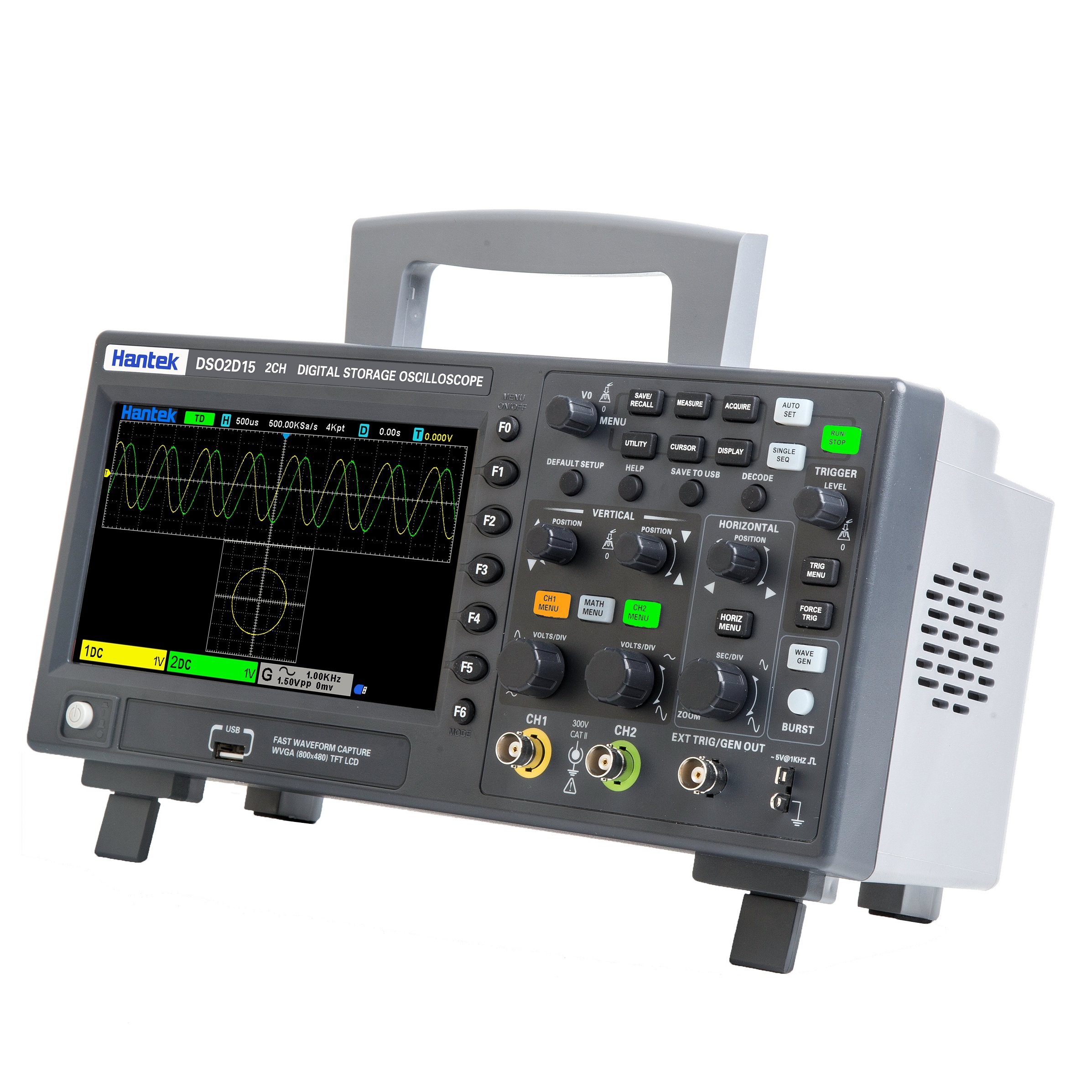
X-Y mode
Supports dual window display in X-Y format.
Specifications:
| Model | DSO2D15 | DSO2D10 (this model) | DSO2C15 | DSO2C10 |
| Bandwidth | 150MHz | 100MHz | 150MHz | 100MHz |
| Oscilloscope channels | 2CH | 2CH | 2CH | 2CH |
| Waveform generator | 1CH | 1CH | – | – |
| Oscilloscope | ||||
| Sample rate | 1GSa/s (single channel) 500MSa/s (two channels) | |||
| Acquisition | ||||
| Normal | Sample data | |||
| Peak-to-peak value | Display high frequency and random burr | |||
| Average | Average waveform, times: 4, 8, 16, 32, 64, 128 | |||
| High resolution | Up to 12bit | |||
| Input | ||||
| Input coupling | DC, AC, GND | |||
| Input impedance | 1MΩ±2% ‖13pF±3pF | |||
| Probe attenuation factor | 1X, 10X, 100X, 1000X | |||
| Voltage rating | 300V CAT II | |||
| Maximum input voltage | 300VRMS (10X) | |||
| Horizontal | ||||
| Waveform interpolation | (sin x)/x | |||
| Maximum record length | Single channel maximum 8M | |||
| Two channels maximum 4M | ||||
| Horizontal scale range | 2ns/div~100s/div 1, 2, 5 step by step | |||
| Time base mode | Y-T, X-Y, Roll | |||
| Zero offset | ±0.5 div×minimum time base gear | |||
| Sample Rate and Delay Time Accuracy | ±25ppm | |||
| Delta Time Measurement Accuracy (Full Bandwidth)Sample Rate and Delay Time Accuracy | single-shot, Normal mode ±(1 sample interval+100ppm×reading+0.6ns) | |||
| >16 times averages ±(1 sample interval+100ppm×reading+0.4ns) | ||||
| Sample interval=sec/div÷200 | ||||
| Sample Rate and Delay Time Accuracy | ±50ppm(at any interval greater than 1ms) | |||
| Vertical | ||||
| Model | DSO2D15 | DSO2D10 | DSO2C15 | DSO2C10 |
| Bandwidth | 150MHz | 100MHz | 150MHz | 100MHz |
| Rising time in BNC position (typical) | 2.4ns | 3.5ns | 2.4ns | 3.5ns |
| Vertical resolution | 8 bits resolution, each channel samples simultaneously | |||
| Vertical sensitivity | 2mV/div to 10V/div | |||
| Offset range | ≥ 200mV/div, ±1V; | |||
| <200mV/div ±50V | ||||
| Mathematical operation | +, -, ×, ÷, FFT | |||
| FFT | Window: Rectangle, Hanning, Hamming, Blackman, Bartlett, Flattop | |||
| Bandwidth Limit | 20MHz | |||
| Bass response(-3db) | In BNC position ≤ 10Hz | |||
| Vertical gain accuracy | In ”normal” or ”average” acquisition mode, the accuracy of 10V/div to 10mV/div is ±3%; | |||
| In ”normal” or ”average” acquisition mode, the accuracy of 5mV/div to 2mV/div is ±4% | ||||
| Note: Bandwidth reduced to 6MHz when using a 1X probe |
| Trigger | ||||
| Trigger type | Edge, Pulse width, Video, Slope, Overtime, Window, Pattern, Interval, Under Amp, UART, LIN, CAN, SPI, IIC | |||
| Trigger level range | ±5 divisions from the center of the screen | |||
| Trigger mode | Auto, Normal, single | |||
| Level | CH1~CH2 | ±4 divisions from the center of the screen | ||
| EXT(Only With AWG Model) | 0~3.3V | |||
| Holdoff range | 8ns~10s | |||
| Trigger level accuracy | CH1~CH2 | 0.2 div×volts/div within ±4 divisions from the center of the screen | ||
| EXT(Only With AWG Model) | ±(Set value× 6%+40mV) | |||
| Edge trigger | Slope | Rising edge, falling edge, rising or falling edge | ||
| Signal source | CH1, CH2, EXT(Only With AWG Model) | |||
| Pulse width trigger | Polarity | Positive polarity, negative polarity | ||
| Condition(When) | <, >, !=, = | |||
| Signal source | CH1~CH2, | |||
| Pulse width range | 8ns ~ 10s | |||
| Accuracy | 8ns | |||
| Video trigger | Signal standard | NTSC, PAL | ||
| Signal source | CH1~CH2 | |||
| Synchronization | Scanning line, line number, odd field, even field, all field | |||
| Slope trigger | Slope | rising, falling | ||
| Condition(When) | <, >, !=, = | |||
| Signal source | CH1 ~ CH2 | |||
| Time range | 8ns ~ 10s | |||
| Accuracy | 8ns | |||
| Overtime trigger | Signal source | CH1~CH2, | ||
| Polarity | Positive polarity, negative polarity | |||
| Time range | 8ns ~ 10s | |||
| Accuracy | 8ns | |||
| Window trigger | Signal source | CH1~CH2 | ||
| Pattern trigger | Pattern | 0: low level; 1: high level; X: ignore | ||
| Level(signal source) | CH1~CH2 | |||
| Interval trigger | Slope | rising, falling | ||
| Condition(When) | <, >, !=, = | |||
| Signal source | CH1~CH2 | |||
| Time range | 8ns ~ 10s | |||
| Accuracy | 8ns | |||
| Under Amp trigger | Polarity | Positive polarity, negative polarity | ||
| Condition(When) | <, >, !=, = | |||
| Signal source | CH1~CH2 | |||
| Time range | 8ns ~ 10s | |||
| Accuracy | 8ns | |||
| UART trigger | Condition(When) | Start, Stop, data, Parity ERR, COM ERR | ||
| Signal source(RX/TX) | CH1~CH2 | |||
| Data format | Hex (hexadecimal) | |||
| Data length | 1 byte | |||
| Data bit width | 5 bit, 6 bit, 7 bit, 8 bit | |||
| Odd-even check | none, odd, even | |||
| Idle level | high, low | |||
| Baud rate (optional) | 110/300/600/1200/2400/4800/9600/14400/19200/38400/57600/115200/230400/380400/460400 bit/s | |||
| Baud rate(user-defined) | 300bit/s~334000bit/s | |||
| LIN trigger | Condition(When) | Interval field, synchronization field, ID field, synchronization error, identifier, ID and data | ||
| Signal source | CH1~CH2 | |||
| Data format | Hex (hexadecimal) | |||
| Baud rate (optional) | 110/300/600/1200/2400/4800/9600/14400/19200/38400/57600/115200/230400/380400/460400 bit/s | |||
| Baud rate(user-defined) | 300bit/s~334000bit/s | |||
| CAN trigger | Condition(When) | Start bit, remote frame ID, data frame ID, frame ID, data frame data, error frame, all errors, ACK Error, overload frame | ||
| Signal source | CH1~CH2 | |||
| Data format | Hex (hexadecimal) | |||
| Baud rate (optional) | 10000, 20000, 33300, 500000, 62500, 83300, 100000, 125000, 250000, 500000, 800000, 1000000 | |||
| Baud rate(user-defined) | 5kbit/s~1Mbit/s | |||
| SPI trigger | Signal source | CH1~CH2 | ||
| Data format | Hex (hexadecimal) | |||
| Data bit width | 4, 8, 16, 24, 32 | |||
| IIC trigger | Signal source (SDA/SCL) | CH1~CH2 | ||
| Data format | Hex (hexadecimal) | |||
| Data index | 0~7 | |||
| When(condition) | Start bit, stop bit, No Ack, address, restart, address and data | |||
| Arbitrary waveform generator | ||
| Channel | 1 | |
| Sample rate | 200MSa/s | |
| Vertical resolution | 12 bits | |
| Maximum frequency | 25 MHz | |
| Standard waveforms | sine, square, ramp, Exp, noise, DC | |
| Arbitrary waveform | Arb1, Arb2, Arb3, Arb4 | |
| Sin | Frequency range | 0.1Hz~25MHz |
| Square/pulse | Frequency range | 0.1Hz~10MHz |
| Triangular wave | Frequency range | 0.1Hz~1MHz |
| Sampling wave | Frequency range | 0.1Hz~1MHz |
| Index | Frequency range | 0.1Hz~5MHz |
| Noise | ||
| Arb1 | Frequency range | 0.1 Hz to 10 MHz |
| Arb2 | Frequency range | 0.1 Hz to 10 MHz |
| Arb3 | Frequency range | 0.1 Hz to 10 MHz |
| Arb4 | Frequency range | 0.1 Hz to 10 MHz |
| Waveform length | 4KSa | |
| Measurement | ||||
| Cursor | Voltage difference between cursors △V | |||
| Time difference between cursors △T | ||||
| Reciprocal of △T, in Hertz (1/△T) | ||||
| Auto measurement | frequency, period, mean, peak-to-peak, RMS, minimum, mixmum, rising time, falling time, + width, – width, base, top, middle, amplitude, overshoot, preshoot, rising edge phase difference, falling edge phase difference, + duty, – duty, period mean, PRMS, FOVshoot, ROVshoot, BWIDTH, FRF, FFR, LRR, LRF, LFR, LFF | |||
| DVM | Data source | CH1, CH2 | ||
| Measurement type | DC RMS | |||
| AC RMS | ||||
| DC | ||||
| Frequency meter | hardware 6 bits frequency meter | |||
| General specifications | ||||
| Display | Display type | 7” diagonal TFT liquid crystal | ||
| Display resolution | 800 (horizontal)*480 (vertical) pixels | |||
| Display colour | 16 million colours (24 bits true colour) | |||
| Persistence time | minimum, 1 s, 5 s, 10 s, 30 s, infinite | |||
| Display type | dot, vector | |||
| Display brightness | adjustable | |||
| Grid type | adjustable | |||
| Grid brightness | adjustable | |||
| Interface | Standard interface | USB Host,USB Device | ||
| General specifications | Probe compensator output | |||
| Output voltage, typical | about 2Vpp input ≥1MΩ load | |||
| Frequency, typical | 1kHz | |||
| Power supply | 100-120VAC RMS(±10%), 45Hzto 440Hz, CATⅡ | |||
| 120-240VAC RMS(±10%), 45Hz to 66Hz, CATⅡ | ||||
| Power consumption | <30W | |||
| Fuse | T, 3.15A, 250V, 5x20mm | |||
| Operating temperature | 0~50 °C (32~122 °F) | |||
| Storage temperature | -40~+71 °C (-40~159.8 °F) | |||
| Humidity | ≤+104℉(≤+40°C): ≤90% relative humidity | |||
| 106℉~122℉ (+41°C ~50°C): ≤60% relative humidity | ||||
| Altitude | Operating and nonoperating | 3, 000m (10, 000 feet) | ||
| Mechanical shock | Random vibration | 0.31 g RMS from 50Hz to 500Hz, | ||
| 10 minutes on each axis | ||||
| Nonoperating | 2.46g RMS from 5Hz to 500Hz, | |||
| 10 minutes on each axis | ||||
| Operating | 50g, 11ms, half-sine wave | |||
| Mechanical | Size | 318 x 110 x 150mm (length x width x height) | ||
| Weight | 1900g | |||
Additional information
| Weight | 2.9 kg |
|---|---|
| Dimensions | 39 × 25 × 22 cm |
| Bandwidth | 100MHz |
| Channels | 2 |
| Power Source | Mains |
| Max Sample Rate | 1 GSa/s |
| Max Memory Depth | 8 Mpts |
| Touch Screen | No |
| Waveform Generator | Yes |
You may also like…
-
NZ Stock
Sale!
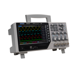
Hantek DSO4254B 250mhz Oscilloscope 4 Channel
Original price was: $1,440.94.$998.20Current price is: $998.20. incl. GST Add to cart -
NZ Stock
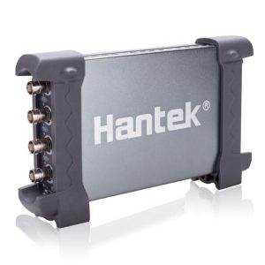
Hantek 6104BD Oscilloscope 4 Channel with AWG
$741.73 incl. GST Add to cart -
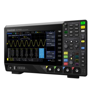
Hantek 4 Channel 200MHz DPO Oscilloscope
$1,647.47 incl. GST Add to cart -
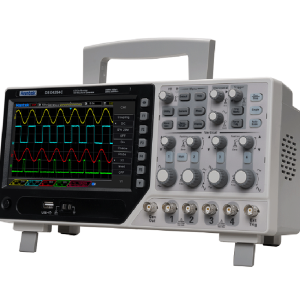
Hantek DSO4254C Oscilloscope 4 Channel
$1,394.33 incl. GST Add to cart
Related products
-
NZ Stock
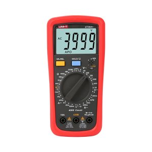
UNI-T UT39A+ CAT III 600V AC/DC Digital Handheld Multimeter
$61.80 incl. GST Add to cart -
NZ Stock
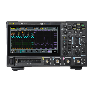
Rigol DHO914S 4 Channel 125MHz Oscilloscope + AWG
$2,067.70 incl. GST Add to cart -
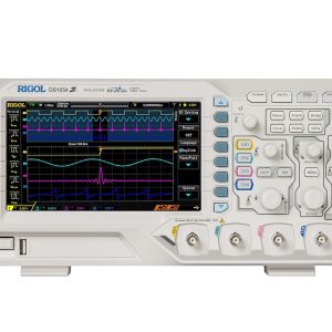
Rigol DS1054Z 50MHz 4CH Digital Storage Oscilloscope
$1,344.38 incl. GST Read more -
Hantek 5.5 Digit Precision Digital Bench Multimeter HDM3055
$945.22 incl. GST Add to cart

Reviews
There are no reviews yet