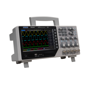
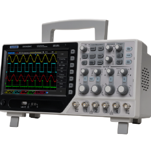
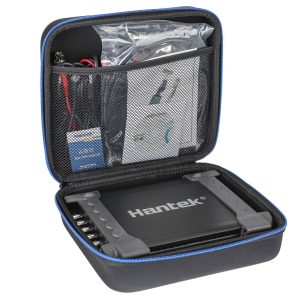
Hantek 100MHz DSO2C10 Dual Channel Digital Oscilloscope
Sale!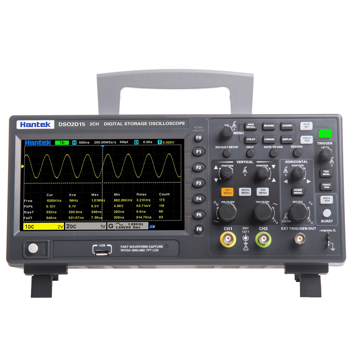
Buy it now
Original price was: $659.00.$562.99Current price is: $562.99. incl. GST
![]() In Stock in NZ
In Stock in NZ
The Hantek DSO2000 Series Oscilloscopes are great all-rounders for the bench. We’ve used the DSO2C10 for audio repairs, power supply troubleshooting, and general electronics work, and it handles everything smoothly. The decent bandwidth and 1GSa/s sampling rate are more than enough for most hobby and light professional tasks.
It’s compact, easy to use, and the screen is crisp and responsive. Built-in serial decoding and USB connectivity are nice extras at this price point. For everyday tinkering, repairs, and testing, it’s a reliable and affordable scope that gets the job done.
Video
Description
- 2 channels with independent control knobs
- 100 MHz analog channel bandwidth options
- Sampling rate up to 1 GSa/s
- 8M memory depth for waveform accuracy
- Vertical range 2mV/div to 10V/div
- Vertical resolution: 8-bit
- Advanced trigger modes: Edge, Pulse, Video, Slope, Overtime, Window, Pattern, Interval, Under Amp, UART, LIN, CAN, SPI, IIC
- Serial bus decode and protocol analysis: RS232/UART, I2C, SPI, CAN, LIN
- Supports multiple data formats: settings, waveforms, reference waveforms, CSV, images
- 3-digit digital voltmeter and 6-digit hardware frequency counter
- 32 auto measurements with statistics (max, min, standard deviation, etc.)
- 2 sets of digital voltmeters
- Threshold testing and free on-screen measurements
- Supports SCPI remote command control
- USB Host/Device connectivity
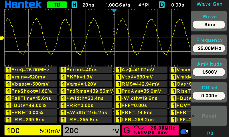
32 kinds of auto measurements with statistics
Save and export data
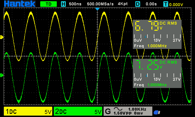
Digital voltmeter functions
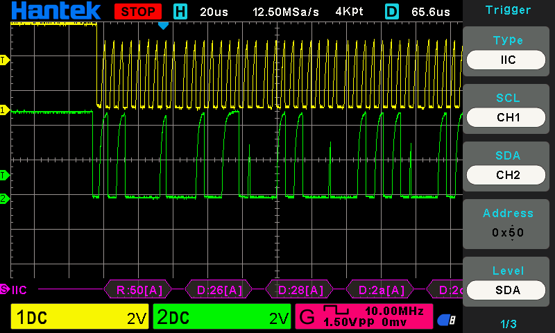
Serial bus trigger and decode
8M memory depth
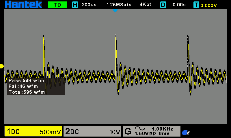
PASS/FAIL testing
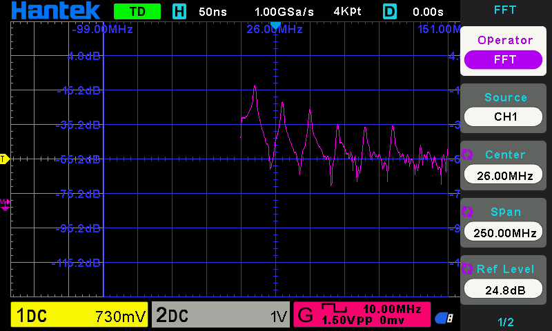
Math operations and FFT
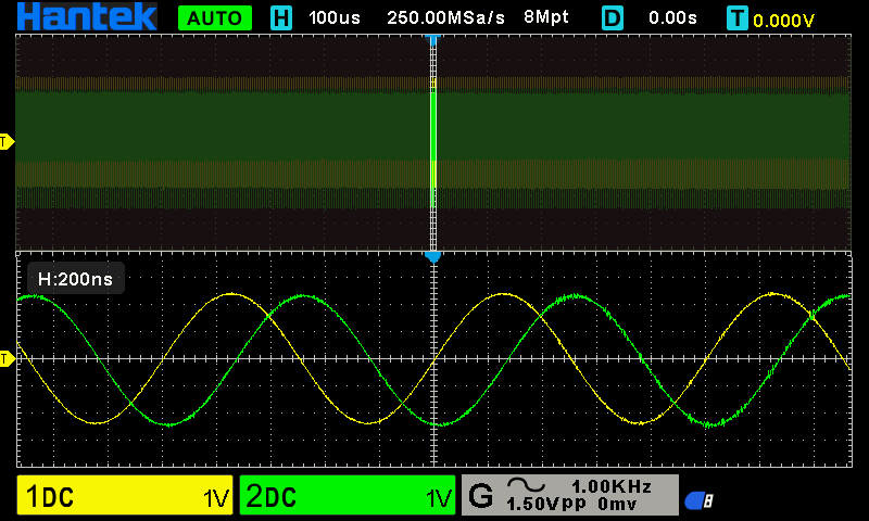
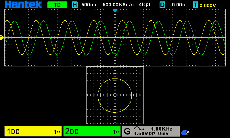
X-Y mode
Specifications:
| Model | DSO2D15 | DSO2D10 | DSO2C15 | DSO2C10 (this model) |
| Bandwidth | 150MHz | 100MHz | 150MHz | 100MHz |
| Oscilloscope channels | 2CH | 2CH | 2CH | 2CH |
| Waveform generator | 1CH | 1CH | – | – |
| Oscilloscope | ||||
| Sample rate | 1GSa/s (single channel) 500MSa/s (two channels) | |||
| Acquisition | ||||
| Normal | Sample data | |||
| Peak-to-peak value | Display high frequency and random burr | |||
| Average | Average waveform, times: 4, 8, 16, 32, 64, 128 | |||
| High resolution | Up to 12bit | |||
| Input | ||||
| Input coupling | DC, AC, GND | |||
| Input impedance | 1MΩ±2% ‖13pF±3pF | |||
| Probe attenuation factor | 1X, 10X, 100X, 1000X | |||
| Voltage rating | 300V CAT II | |||
| Maximum input voltage | 300VRMS (10X) | |||
| Horizontal | ||||
| Waveform interpolation | (sin x)/x | |||
| Maximum record length | Single channel maximum 8M | |||
| Two channels maximum 4M | ||||
| Horizontal scale range | 2ns/div~100s/div 1, 2, 5 step by step | |||
| Time base mode | Y-T, X-Y, Roll | |||
| Zero offset | ±0.5 div×minimum time base gear | |||
| Sample Rate and Delay Time Accuracy | ±25ppm | |||
| Delta Time Measurement Accuracy (Full Bandwidth)Sample Rate and Delay Time Accuracy | single-shot, Normal mode ±(1 sample interval+100ppm×reading+0.6ns) | |||
| >16 times averages ±(1 sample interval+100ppm×reading+0.4ns) | ||||
| Sample interval=sec/div÷200 | ||||
| Sample Rate and Delay Time Accuracy | ±50ppm(at any interval greater than 1ms) | |||
| Vertical | ||||
| Model | DSO2D15 | DSO2D10 | DSO2C15 | DSO2C10 |
| Bandwidth | 150MHz | 100MHz | 150MHz | 100MHz |
| Rising time in BNC position (typical) | 2.4ns | 3.5ns | 2.4ns | 3.5ns |
| Vertical resolution | 8 bits resolution, each channel samples simultaneously | |||
| Vertical sensitivity | 2mV/div to 10V/div | |||
| Offset range | ≥ 200mV/div, ±1V; | |||
| <200mV/div ±50V | ||||
| Mathematical operation | +, -, ×, ÷, FFT | |||
| FFT | Window: Rectangle, Hanning, Hamming, Blackman, Bartlett, Flattop | |||
| Bandwidth Limit | 20MHz | |||
| Bass response(-3db) | In BNC position ≤ 10Hz | |||
| Vertical gain accuracy | In ”normal” or ”average” acquisition mode, the accuracy of 10V/div to 10mV/div is ±3%; | |||
| In ”normal” or ”average” acquisition mode, the accuracy of 5mV/div to 2mV/div is ±4% | ||||
| Note: Bandwidth reduced to 6MHz when using a 1X probe |
| Trigger | ||||
| Trigger type | Edge, Pulse width, Video, Slope, Overtime, Window, Pattern, Interval, Under Amp, UART, LIN, CAN, SPI, IIC | |||
| Trigger level range | ±5 divisions from the center of the screen | |||
| Trigger mode | Auto, Normal, single | |||
| Level | CH1~CH2 | ±4 divisions from the center of the screen | ||
| EXT(Only With AWG Model) | 0~3.3V | |||
| Holdoff range | 8ns~10s | |||
| Trigger level accuracy | CH1~CH2 | 0.2 div×volts/div within ±4 divisions from the center of the screen | ||
| EXT(Only With AWG Model) | ±(Set value× 6%+40mV) | |||
| Edge trigger | Slope | Rising edge, falling edge, rising or falling edge | ||
| Signal source | CH1, CH2, EXT(Only With AWG Model) | |||
| Pulse width trigger | Polarity | Positive polarity, negative polarity | ||
| Condition(When) | <, >, !=, = | |||
| Signal source | CH1~CH2, | |||
| Pulse width range | 8ns ~ 10s | |||
| Accuracy | 8ns | |||
| Video trigger | Signal standard | NTSC, PAL | ||
| Signal source | CH1~CH2 | |||
| Synchronization | Scanning line, line number, odd field, even field, all field | |||
| Slope trigger | Slope | rising, falling | ||
| Condition(When) | <, >, !=, = | |||
| Signal source | CH1 ~ CH2 | |||
| Time range | 8ns ~ 10s | |||
| Accuracy | 8ns | |||
| Overtime trigger | Signal source | CH1~CH2, | ||
| Polarity | Positive polarity, negative polarity | |||
| Time range | 8ns ~ 10s | |||
| Accuracy | 8ns | |||
| Window trigger | Signal source | CH1~CH2 | ||
| Pattern trigger | Pattern | 0: low level; 1: high level; X: ignore | ||
| Level(signal source) | CH1~CH2 | |||
| Interval trigger | Slope | rising, falling | ||
| Condition(When) | <, >, !=, = | |||
| Signal source | CH1~CH2 | |||
| Time range | 8ns ~ 10s | |||
| Accuracy | 8ns | |||
| Under Amp trigger | Polarity | Positive polarity, negative polarity | ||
| Condition(When) | <, >, !=, = | |||
| Signal source | CH1~CH2 | |||
| Time range | 8ns ~ 10s | |||
| Accuracy | 8ns | |||
| UART trigger | Condition(When) | Start, Stop, data, Parity ERR, COM ERR | ||
| Signal source(RX/TX) | CH1~CH2 | |||
| Data format | Hex (hexadecimal) | |||
| Data length | 1 byte | |||
| Data bit width | 5 bit, 6 bit, 7 bit, 8 bit | |||
| Odd-even check | none, odd, even | |||
| Idle level | high, low | |||
| Baud rate (optional) | 110/300/600/1200/2400/4800/9600/14400/19200/38400/57600/115200/230400/380400/460400 bit/s | |||
| Baud rate(user-defined) | 300bit/s~334000bit/s | |||
| LIN trigger | Condition(When) | Interval field, synchronization field, ID field, synchronization error, identifier, ID and data | ||
| Signal source | CH1~CH2 | |||
| Data format | Hex (hexadecimal) | |||
| Baud rate (optional) | 110/300/600/1200/2400/4800/9600/14400/19200/38400/57600/115200/230400/380400/460400 bit/s | |||
| Baud rate(user-defined) | 300bit/s~334000bit/s | |||
| CAN trigger | Condition(When) | Start bit, remote frame ID, data frame ID, frame ID, data frame data, error frame, all errors, ACK Error, overload frame | ||
| Signal source | CH1~CH2 | |||
| Data format | Hex (hexadecimal) | |||
| Baud rate (optional) | 10000, 20000, 33300, 500000, 62500, 83300, 100000, 125000, 250000, 500000, 800000, 1000000 | |||
| Baud rate(user-defined) | 5kbit/s~1Mbit/s | |||
| SPI trigger | Signal source | CH1~CH2 | ||
| Data format | Hex (hexadecimal) | |||
| Data bit width | 4, 8, 16, 24, 32 | |||
| IIC trigger | Signal source (SDA/SCL) | CH1~CH2 | ||
| Data format | Hex (hexadecimal) | |||
| Data index | 0~7 | |||
| When(condition) | Start bit, stop bit, No Ack, address, restart, address and data | |||
| Measurement | ||||
| Cursor | Voltage difference between cursors △V | |||
| Time difference between cursors △T | ||||
| Reciprocal of △T, in Hertz (1/△T) | ||||
| Auto measurement | frequency, period, mean, peak-to-peak, RMS, minimum, mixmum, rising time, falling time, + width, – width, base, top, middle, amplitude, overshoot, preshoot, rising edge phase difference, falling edge phase difference, + duty, – duty, period mean, PRMS, FOVshoot, ROVshoot, BWIDTH, FRF, FFR, LRR, LRF, LFR, LFF | |||
| DVM | Data source | CH1, CH2 | ||
| Measurement type | DC RMS | |||
| AC RMS | ||||
| DC | ||||
| Frequency meter | hardware 6 bits frequency meter | |||
| General specifications | ||||
| Display | Display type | 7” diagonal TFT liquid crystal | ||
| Display resolution | 800 (horizontal)*480 (vertical) pixels | |||
| Display colour | 16 million colours (24 bits true colour) | |||
| Persistence time | minimum, 1 s, 5 s, 10 s, 30 s, infinite | |||
| Display type | dot, vector | |||
| Display brightness | adjustable | |||
| Grid type | adjustable | |||
| Grid brightness | adjustable | |||
| Interface | Standard interface | USB Host,USB Device | ||
| General specifications | Probe compensator output | |||
| Output voltage, typical | about 2Vpp input ≥1MΩ load | |||
| Frequency, typical | 1kHz | |||
| Power supply | 100-120VAC RMS(±10%), 45Hzto 440Hz, CATⅡ | |||
| 120-240VAC RMS(±10%), 45Hz to 66Hz, CATⅡ | ||||
| Power consumption | <30W | |||
| Fuse | T, 3.15A, 250V, 5x20mm | |||
| Operating temperature | 0~50 °C (32~122 °F) | |||
| Storage temperature | -40~+71 °C (-40~159.8 °F) | |||
| Humidity | ≤+104℉(≤+40°C): ≤90% relative humidity | |||
| 106℉~122℉ (+41°C ~50°C): ≤60% relative humidity | ||||
| Altitude | Operating and nonoperating | 3, 000m (10, 000 feet) | ||
| Mechanical shock | Random vibration | 0.31 g RMS from 50Hz to 500Hz, | ||
| 10 minutes on each axis | ||||
| Nonoperating | 2.46g RMS from 5Hz to 500Hz, | |||
| 10 minutes on each axis | ||||
| Operating | 50g, 11ms, half-sine wave | |||
| Mechanical | Size | 318 x 110 x 150mm (length x width x height) | ||
| Weight | 1900g | |||
Additional information
| Weight | 2.9 kg |
|---|---|
| Dimensions | 39 × 25 × 22 cm |
| Bandwidth | 100MHz |
| Channels | 2 |
| Power Source | Mains |
| Max Sample Rate | 1 GSa/s |
| Max Memory Depth | 8 Mpts |
You may also like…
-
NZ Stock
Hantek 6104BD Oscilloscope 4 Channels with Arbitrary Waveform Generator 100MHz Bandwidth Powered by USB
$762.20 incl. GST Add to cart -
NZ Stock
Hantek DSO4254B 250mhz Digital Storage Oscilloscope 4 Channels
$1,223.31 incl. GST Add to cart -
Hantek DSO4254C Oscilloscope 4 Channels, 250MHz, 1GS/s + Waveform Generator
$1,311.86 incl. GST Add to cart
Related products
-
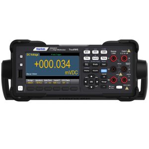
Hantek 5.5 Digit Precision Digital Bench Multimeter HDM3055
$890.32 incl. GST Add to cart -
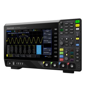
Hantek 4 Channel 200MHz 2GSa/s 2MGpts DPO Oscilloscope, AWG & 16 Channel Logic Analyser
$1,823.70 incl. GST Add to cart -
NZ Stock
YIHUA 982D Professional Rapidly Heating Soldering Iron Station
$283.94 incl. GST Add to cart -
Hantek Automotive Diagnostic USB Oscilloscope 8 Channels
$389.11 incl. GST Add to cart
Reviews
There are no reviews yet.